Hi Rob,
The previous owner has said fully rebuilt, but he did not say rebuilt by someone who knew what he was doing.
Unfortunately Triumph Meriden does not help, unlike the Japanese, they give you the opportunity to get things wrong by having items that need to be set exactly to succeed making the bike run sweetly, then never giving you the tolerances or detailing the methods to set them up correctly. (Pushrod tube seals is a good example) Fortunately there were some owners and some agents that worked things out, and some generous enough to share their hard won knowledge (John Healy with Vintage Bike Magazine comes to mind here).
Then Tim Berners Lee/ Al Gore and others let the internet escape from a military project into the real world, and here we are.
The Torrington needle roller bearings if set up correctly are very long lived, with enough internal clearance to allow minor misalignment. It is rare they have problems unless set up badly.
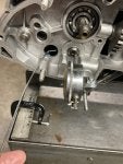
Looking at your photo, it looks like most of the debris is from the bearing.
The set up needs to be quite precise. It looks to me that the bearings were not installed far enough into the case.
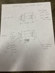
1)The amount sticking out does two things, it sets the base end float clearance of the layshaft, it holds the thrust washer in position.
2) The bearing edge should never touch the layshaft, the bearing edge should sit just below the surface of the thrust washer. If the bearing does not stick out enough, the thrust washer falls off and can jam or it works off the pin and can either jam or spin.
If the bearing sticks out too far then the layshaft runs on the edge of the bearing destroying it, this is what I believe happened in your gearbox.
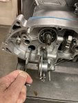
3) The photo of the inner case looks terrible, but I think a lot of that detritus is from the bearing, not from the case.
Once that is out of the way I think you will find the surface is not too bad. The case does not have to do much except butt up against the thrust washer, I think you might get away with smoothing it square to the bearing.
4) The pin that stops the thrust washer spinning, like the bearing has to stick out so far so the thrust washer is prevented from spinning, but not so far that it extends past the thrust washer and contacts the layshaft.
If the pin will not come out then drill a new hole opposite the original. I have used a thrust washer as a drill template and a roll pin as a replacement before now. The pin can be ground to length after fitting.
5) Setting up the layshaft, Triumph Meriden are no help here, they give no information, so you get to judge it yourself.
You will need to insert and remove the layshaft several times to set the end float, luckily you can leave all of the gears and selector fork (not 4th/5th).
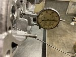
fit the layshaft and thrust washers including inner gasket. Measure the end float, I use a dial gauge and a magnet on the end of the shaft to push and pull the layshaft. Take the reading.
I like to have between 3 and 5 thou clearance, this is quite tight but gives a fantastic gearchange, and gives confidence that the thrust washer will stay in place, there is no guidance from Triumph on this. The gearbox will still work with much larger end float.
You have two main ways of altering the end float, make (or have made) thicker or thinner thrust washers, or fit thicker or thinner gaskets between the engine case and the outer gearbox cover. Your gearbox was designed for a gasket, earlier models were not.
6) Once the layshaft end float is set, then the gearbox can be built.
If you have altered the gasket thickness, then the primary chain alignment between engine sprocket and clutch should be checked/reset.
regards
Peg.
PS.
If you know the thickness of the thrust washer you need and can find a parts supplier with stock (This is difficult now in these internet supply times), you could ask if you can use a micrometer to check each one, there are some large variations in thickness.