

Foreword: This is a reference thread only - for discussion and general Q&A regarding Generating System issues, please contribute to this thread
Subsequent to originally writing this thread, my current endorsement for best choice R/R replacement is the Shindengen SH847 Series R/R (scroll down towards bottom for details)
MOSFET R/R are a great reliability improvement on the OEM SCR type R/R, in its own right as the R/R device.
However they do nothing to add reliability to the stator, whereas the Series Style greatly enhances this aspect.
A Series R/R significantly reduces the load on the stator which will run close to half of the current as it would with a Shunt R/R (whether that be SCR or MOSFET)
Ergo the stator runs less hot and reliability is significantly improved.
This mod applies equally to most modern bikes regardless of the marque/model.
The defining factor regardless of motorcycle brand/year/model is that your bike has the discreet 3-phase Stator/Generator and Rectifier/Regulator arrangement
As a preliminary, acknowledgements due to OldnDumb and CLB for their previous inputs on this subject.
This is about replacing the standard equipment Regulator/Rectifier with a more efficient component. You can do this in event of failure rather than replace with the same stock component, or you can even do as a preventive measure if desired.
As a prologue, let me introduce a basic troubleshooting process to determine whether you have a charging system failure.
Diagnostics:
A good Multi-meter is a pre-requisite.
Record your battery voltage under the follow conditions
1) Ignition off, unloaded battery.
2) Ignition on, headlights on, not running
3) Bike started, running at idle
For condition 1, should be at least in the high 12.x range if fully charged.
In condition 2, your voltage should not drop much below 12.0 at worst. (It may continue to drop – hopefully slowly! – as your lights will be discharging it. However this should be a slow decline)
If it does drop immediately into the 11’s, your battery is insufficiently charged – if it was just charged from a battery charger however, then it indicates your battery no longer has sufficient capacity to retain charge/supply current to load and should be replaced.
Condition 3 is what we are most interested in with respect to charging capability.
Voltage should be at least in the 13’s at all engine rpm. You may detect it will fall off slightly as you raise engine rpm. This is not atypical performance. A simple mod that can enhance your charging voltage to the battery can be achieved by this modification outlined in this thread. That should give you performance in the 14V+ range.
What if you have less than 13V?
First thing to check is the fuse in the charging circuit. Ask on the forum for your particular model which one you should check if in doubt.
Next, examine the wires and connectors between the stator output and the R/R input (three wire harness and connectors) – are these charred/melted due to excessive heating? This is fairly common result of poor connection between the mating terminals. See later in thread for examples of this issue & suggested replacements.
A ‘cold’ resistance check for shorted diode/SCR:
Unplug both input & output plugs from R/R;
With your meter set to read resistance (use a diode test if the your multi-meter has one), test from each pin of the three pin plug, to both the red & black wired pins of the 4-pin plug; NONE of these should read short circuit (zero resistance); depending which way you bias the test leads, you may get some reading (from the forward bias of the component) but it must absolutely not be a short. If you see a short on any of these readings the R/R is defective.
Next, do a resistance check on the stator (check at the cable connector going back towards the stator itself).
This test is typically unlikely to show any definitive issue, whether good or bad - unless there is a complete open circuit to one pin, perhaps indicating broken wire connection
Some guides suggest you can see a difference between the readings if there is a burned coil - highly unlikely that you have a meter that is capable of differentiating.
So really just looking for basic continuity here.
Measure between the three respective combinations of the three pins:
1-2
2-3
3-1
This time each of these should measure almost short circuit (very low resistance in order or about 1 ohm)
This next check is probably the simplest/quickest way of determining a stator problem
- in majority of cases a bad stator will be indicated by failing following test:
Check resistance from any one pin to the engine ground terminal – this should not read any indication – maximum resistance or open-circuit.
If you read ‘short’ in that last test, then your stator is bad.
(if open, it is not quite guaranteed your stator is good however - but in majority of cases a failed stator will fail this isolation test)
An additional test you can do (but honestly the isolation test above will indicate a pretty conclusive pass or fail):
Check the AC voltage output from the stator with engine running:
Leave stator disconnected from the R/R and start the engines.
With meter set to read AC Volts check
1-2
2-3
3-1
All three should be the same value – any significant difference of one reading will indicate a bad phase and the stator is probably defective.
At idle this should be ~ 20V* and rise to ~ 70V* at 5K rpm.
I hesitate to use absolute numbers here as this can be different between models and test equipment and especially the engine rpm!
What you are looking for is same value between phases and like increase on each phase as rpm increases.
If any of the above tests raises suspicion, pull the cover & inspect the stator. It is simple to do and can set your mind at ease by seeing what it looks like. Hopefully NOT with 1/3 of it a black charred mess!
If you have to replace the stator and R/R, especially because of a shorted R/R and excess current drain, be especially careful to ensure that your wiring has not been compromised. Replace any cable &/or connector plug that is not in optimum condition.
One of the best sources for a replacement Stator (and my recommendation) is Ricks MotorSport Electrics (link)
Now on to the alternative R/R replacement
Preface: When this thread first written, there really wasn't a good Series Regulator widely available as a replacement candidate. Now there are a couple of options that are in play.
This thread is read by many non-Triumph owners so I will define the replacement strategy into two groups
1: If your bike marque/model generally has a robust stator with low failure rate amongst the population, then MOSFET Regulator remains a good reliability improvement for high-failure SCR Shunt Regulators.
2. If your bike marque/model suffers from a relatively high failure rate in the general population, then MOSFET Regulator will do NOTHING to improve this situation and selection of a Series* style Regulator becomes a much better choice.
* The short version is that a Series Regulator will run much lower current in the stator and so it will have the stator itself producing lower dissipated power, run cooler and be more reliable.
Generally, a much better device regarding the reliability of the stator. The only downside - until recently - has been cost vs good value MOSFET Shunt units. However that 'value' is achieved if stator replacement does not have to be added to the equation!
For more on Series Regulators read on down towards bottom of thread.
MOSFET SHUNT REGULATORS
Best widely available MOSFET Shunt R/R on the market today is the Shindengen FH012AA* used on the late (06+) Yamaha FJR, 07+ Yamaha R1 among others
What makes it better is that is a MOSFET controlled device rather than the crude SCR shunt type that is on most bikes until recently and also is a 50A rated device.
MUCH better voltage regulation and runs cooler too due to more efficient devices and control circuitry.
* Recently superseded by FH020
The SCR shunt type consumes more energy in the Regulator itself than the bike is using and dumps a ton of current into the heatsink (feel yours & just see how hot those things run!!!! - don't touch it - you'll burn yourself - seriously!) The problem is exacerbated because their efficiency goes even lower when they get HOT so it's a vicious circle. Heat is the number 1 killer of these devices.
Incidentally its a misconception that shunt type work harder with increased load i.e. higher-wattage lights, heated vests etc - actually, the higher the load on the output, the less work the shunt regulator does in dumping that excess energy and will actually run cooler!!
The FET has extremely low resistance in conducting state and this results in a lower dissipated power from the device while conducting load current, as opposed to the SCR which shunts the maximum current across a significant volt drop, resulting in a higher dissipated power - and resulting temperature, much more so than the FET device.
You can install this unit on your Triumph Sprint, S3, Daytona, TT600, Tiger; Suzuki TL, SV 650, SV1K;
or indeed ANY bike that has discreet three-phase stator and R/R arrangement.
![Image]()

![Image]()
These are starting to show up on the EBay market - there are many other bike models, simplest check is to use something like Ron Ayers to find all the match models. (Even Grizzly ATV uses it) I paid $32 plus shipping for mine. They are regularly available for < $50
The OEM Yamaha part number is 1D7-81960-00-00
On Ron Ayers website, there is a feature called where is it used
- enter that part number and it will give list of all the models/years that it is utilized on. Then when you find one on EBay you can validate it is the FH012.
Currently, lowest price (at time of writing) for brand new is from MRCycles at $136 plus shipping
Have the FH012 on the TL, and just converted the Triumph Daytona with same and ultimately the SV650 (which will receive the FH008 shown below).
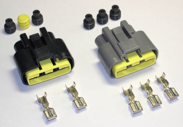
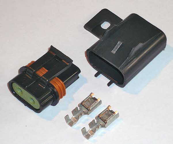
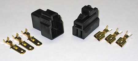
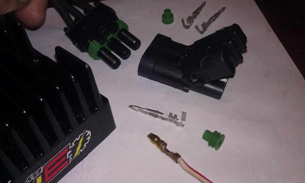
The connector plugs are quite different to the OEM Triumph of course - SEE POST #6 FOR UPDATE ON SOURCE FOR THE CONNECTOR PLUGS
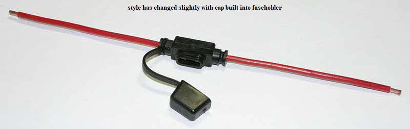
The best connection method IMO is to run the output leads directly to the battery (the '+' via a 30A fuse) - that minimizes any losses & you get the 'sensing' voltage directly at the battery terminals.
This is on a Triumph Sprint (coutesy of OldnDumb) - my TL & S3/Daytona installations are further down.
![Image]()
Another alternative that has MOSFET control, is the FH010 - this is used on late-model Kawasakis (ZZX10 /14).
I'm not sure of the power rating compared to the 012 (unable to find exact specs for it) but expect it would be similar to the 012 and should still be plenty for the Triumphs.
That 010 unit has same form factor as the 012.
* The FH012 has now been superceded by the FH020
Mechanical Installation:
Note that pitch between the mounting holes on the FH010 or FH012 is 70mm - the Triumph OEM are ~ 80mm
You can simply 'slot' the holes in the R/R heatsink body using a rat-tail file or Dremel to allow the bolts to align to the original mounting holes.
This will help satisfy the mounting requirements in the majority of cases.
In some other models, it may be necessary to fabricate an adapter plate.
Subsequent to originally writing this thread, my current endorsement for best choice R/R replacement is the Shindengen SH847 Series R/R (scroll down towards bottom for details)
MOSFET R/R are a great reliability improvement on the OEM SCR type R/R, in its own right as the R/R device.
However they do nothing to add reliability to the stator, whereas the Series Style greatly enhances this aspect.
A Series R/R significantly reduces the load on the stator which will run close to half of the current as it would with a Shunt R/R (whether that be SCR or MOSFET)
Ergo the stator runs less hot and reliability is significantly improved.
This mod applies equally to most modern bikes regardless of the marque/model.
The defining factor regardless of motorcycle brand/year/model is that your bike has the discreet 3-phase Stator/Generator and Rectifier/Regulator arrangement
As a preliminary, acknowledgements due to OldnDumb and CLB for their previous inputs on this subject.
This is about replacing the standard equipment Regulator/Rectifier with a more efficient component. You can do this in event of failure rather than replace with the same stock component, or you can even do as a preventive measure if desired.
As a prologue, let me introduce a basic troubleshooting process to determine whether you have a charging system failure.
Diagnostics:
A good Multi-meter is a pre-requisite.
Record your battery voltage under the follow conditions
1) Ignition off, unloaded battery.
2) Ignition on, headlights on, not running
3) Bike started, running at idle
For condition 1, should be at least in the high 12.x range if fully charged.
In condition 2, your voltage should not drop much below 12.0 at worst. (It may continue to drop – hopefully slowly! – as your lights will be discharging it. However this should be a slow decline)
If it does drop immediately into the 11’s, your battery is insufficiently charged – if it was just charged from a battery charger however, then it indicates your battery no longer has sufficient capacity to retain charge/supply current to load and should be replaced.
Condition 3 is what we are most interested in with respect to charging capability.
Voltage should be at least in the 13’s at all engine rpm. You may detect it will fall off slightly as you raise engine rpm. This is not atypical performance. A simple mod that can enhance your charging voltage to the battery can be achieved by this modification outlined in this thread. That should give you performance in the 14V+ range.
What if you have less than 13V?
First thing to check is the fuse in the charging circuit. Ask on the forum for your particular model which one you should check if in doubt.
Next, examine the wires and connectors between the stator output and the R/R input (three wire harness and connectors) – are these charred/melted due to excessive heating? This is fairly common result of poor connection between the mating terminals. See later in thread for examples of this issue & suggested replacements.
A ‘cold’ resistance check for shorted diode/SCR:
Unplug both input & output plugs from R/R;
With your meter set to read resistance (use a diode test if the your multi-meter has one), test from each pin of the three pin plug, to both the red & black wired pins of the 4-pin plug; NONE of these should read short circuit (zero resistance); depending which way you bias the test leads, you may get some reading (from the forward bias of the component) but it must absolutely not be a short. If you see a short on any of these readings the R/R is defective.
Next, do a resistance check on the stator (check at the cable connector going back towards the stator itself).
This test is typically unlikely to show any definitive issue, whether good or bad - unless there is a complete open circuit to one pin, perhaps indicating broken wire connection
Some guides suggest you can see a difference between the readings if there is a burned coil - highly unlikely that you have a meter that is capable of differentiating.
So really just looking for basic continuity here.
Measure between the three respective combinations of the three pins:
1-2
2-3
3-1
This time each of these should measure almost short circuit (very low resistance in order or about 1 ohm)
This next check is probably the simplest/quickest way of determining a stator problem
- in majority of cases a bad stator will be indicated by failing following test:
Check resistance from any one pin to the engine ground terminal – this should not read any indication – maximum resistance or open-circuit.
If you read ‘short’ in that last test, then your stator is bad.
(if open, it is not quite guaranteed your stator is good however - but in majority of cases a failed stator will fail this isolation test)
An additional test you can do (but honestly the isolation test above will indicate a pretty conclusive pass or fail):
Check the AC voltage output from the stator with engine running:
Leave stator disconnected from the R/R and start the engines.
With meter set to read AC Volts check
1-2
2-3
3-1
All three should be the same value – any significant difference of one reading will indicate a bad phase and the stator is probably defective.
At idle this should be ~ 20V* and rise to ~ 70V* at 5K rpm.
I hesitate to use absolute numbers here as this can be different between models and test equipment and especially the engine rpm!
What you are looking for is same value between phases and like increase on each phase as rpm increases.
If any of the above tests raises suspicion, pull the cover & inspect the stator. It is simple to do and can set your mind at ease by seeing what it looks like. Hopefully NOT with 1/3 of it a black charred mess!
If you have to replace the stator and R/R, especially because of a shorted R/R and excess current drain, be especially careful to ensure that your wiring has not been compromised. Replace any cable &/or connector plug that is not in optimum condition.
One of the best sources for a replacement Stator (and my recommendation) is Ricks MotorSport Electrics (link)
Now on to the alternative R/R replacement
Preface: When this thread first written, there really wasn't a good Series Regulator widely available as a replacement candidate. Now there are a couple of options that are in play.
This thread is read by many non-Triumph owners so I will define the replacement strategy into two groups
1: If your bike marque/model generally has a robust stator with low failure rate amongst the population, then MOSFET Regulator remains a good reliability improvement for high-failure SCR Shunt Regulators.
2. If your bike marque/model suffers from a relatively high failure rate in the general population, then MOSFET Regulator will do NOTHING to improve this situation and selection of a Series* style Regulator becomes a much better choice.
* The short version is that a Series Regulator will run much lower current in the stator and so it will have the stator itself producing lower dissipated power, run cooler and be more reliable.
Generally, a much better device regarding the reliability of the stator. The only downside - until recently - has been cost vs good value MOSFET Shunt units. However that 'value' is achieved if stator replacement does not have to be added to the equation!
For more on Series Regulators read on down towards bottom of thread.
MOSFET SHUNT REGULATORS
Best widely available MOSFET Shunt R/R on the market today is the Shindengen FH012AA* used on the late (06+) Yamaha FJR, 07+ Yamaha R1 among others
What makes it better is that is a MOSFET controlled device rather than the crude SCR shunt type that is on most bikes until recently and also is a 50A rated device.
MUCH better voltage regulation and runs cooler too due to more efficient devices and control circuitry.
* Recently superseded by FH020
The SCR shunt type consumes more energy in the Regulator itself than the bike is using and dumps a ton of current into the heatsink (feel yours & just see how hot those things run!!!! - don't touch it - you'll burn yourself - seriously!) The problem is exacerbated because their efficiency goes even lower when they get HOT so it's a vicious circle. Heat is the number 1 killer of these devices.
Incidentally its a misconception that shunt type work harder with increased load i.e. higher-wattage lights, heated vests etc - actually, the higher the load on the output, the less work the shunt regulator does in dumping that excess energy and will actually run cooler!!
The FET has extremely low resistance in conducting state and this results in a lower dissipated power from the device while conducting load current, as opposed to the SCR which shunts the maximum current across a significant volt drop, resulting in a higher dissipated power - and resulting temperature, much more so than the FET device.
You can install this unit on your Triumph Sprint, S3, Daytona, TT600, Tiger; Suzuki TL, SV 650, SV1K;
or indeed ANY bike that has discreet three-phase stator and R/R arrangement.


These are starting to show up on the EBay market - there are many other bike models, simplest check is to use something like Ron Ayers to find all the match models. (Even Grizzly ATV uses it) I paid $32 plus shipping for mine. They are regularly available for < $50
The OEM Yamaha part number is 1D7-81960-00-00
On Ron Ayers website, there is a feature called where is it used
- enter that part number and it will give list of all the models/years that it is utilized on. Then when you find one on EBay you can validate it is the FH012.
Currently, lowest price (at time of writing) for brand new is from MRCycles at $136 plus shipping
Have the FH012 on the TL, and just converted the Triumph Daytona with same and ultimately the SV650 (which will receive the FH008 shown below).
The connector plugs are quite different to the OEM Triumph of course - SEE POST #6 FOR UPDATE ON SOURCE FOR THE CONNECTOR PLUGS
The best connection method IMO is to run the output leads directly to the battery (the '+' via a 30A fuse) - that minimizes any losses & you get the 'sensing' voltage directly at the battery terminals.
This is on a Triumph Sprint (coutesy of OldnDumb) - my TL & S3/Daytona installations are further down.

Another alternative that has MOSFET control, is the FH010 - this is used on late-model Kawasakis (ZZX10 /14).
I'm not sure of the power rating compared to the 012 (unable to find exact specs for it) but expect it would be similar to the 012 and should still be plenty for the Triumphs.
That 010 unit has same form factor as the 012.
* The FH012 has now been superceded by the FH020
Mechanical Installation:
Note that pitch between the mounting holes on the FH010 or FH012 is 70mm - the Triumph OEM are ~ 80mm
You can simply 'slot' the holes in the R/R heatsink body using a rat-tail file or Dremel to allow the bolts to align to the original mounting holes.
This will help satisfy the mounting requirements in the majority of cases.
In some other models, it may be necessary to fabricate an adapter plate.


 ) you can read more here -


