Triumph Rat Motorcycle Forums banner

Headlight Performance Improvement

74K views 78 replies 21 participants last post by  needanotherpart  
#1 · (Edited)
This is initially for 97 -04 Speedies and also applies to 97-06 Daytona.

(Actually the circuits for the 99-01 and 02-04 Sprints are almost identical to their respective sistern of similar generations)

Anyone with a 1050 (05+) S3 care to provide some data as to what is happening on those bikes?
(see post # 20 - wiring scheme a little different on the 05+ but I could believe there could be benefits to realize on these models also)

I have previously created threads on other forum regarding the headlight performance of my Suzuki TL and SV650.
Neither of these use relays in the headlight circuits and they suffer for it both in performance & reliability.
Small gauge wiring & no relays means that there is quite a volt-drop to the headlights.

What does the voltage difference at the headlights make?

Check this out from Daniel Stern Lighting
In many cases, the thin factory wires are inadequate even for the stock headlamp equipment.
Headlamp bulb light output is severely compromised with decreased voltage
The drop in light output is not linear, it is exponential with the power.

For example, let's consider a 9006 low beam bulb rated 1000 lumens at 12.8 Volts and plug in different voltages:

10.5V : 510 lumens
11.0V : 597 lumens
11.5V : 695 lumens
12.0V : 803 lumens
12.5V : 923 lumens
12.8V : 1000 lumens ←Rated output voltage
13.0V : 1054 lumens
13.5V : 1198 lumens
14.0V : 1356 lumens ←Rated life voltage
14.5V : 1528 lumens
In simple terms - more volts make more lumens!

Installing relays on my Suzukis made a HUGE difference to the performance - picked up about 2V which translated to about 80% MORE light output!!! :eek:
The lights were immediately brighter & whiter with the same bulbs.
At the same time I also installed a starter-headlight-cut, which is already a standard feature on the Triumphs.

All this while I had been oblivious to any issues regarding the Triumph because Triumph uses relays - except a closer look tells a little different story than first appears.
I recognized that for each headlight, one is powered directly from the dimmer switch and the other is powered by a relay: I was curious to see what the difference might be between each light.

So I did a voltage check on my S3/Daytona hybrid (it actually utlizes Daytona harness mated to S3 headlights - all splices are quality solder joints and am confident these have no bearings on the results)
I was seriously surprised by the results:
I measured 11.5V on one headlight and 12.5V on the other - this with bike running and 14.5V from my Shindengen R/R.
i.e. dropping 2V even on the relay fed light and 3V on the direct wired light!!!

Further investigation showed that part of this drop was solely on the ground return.
I could measure virtually a whole volt (actually 0.995V) at the common terminal at the headlight connector plug with respect to the battery -ve terminal.

So there is clearly 'free' voltage to be had to get better performance from the lighting circuit.

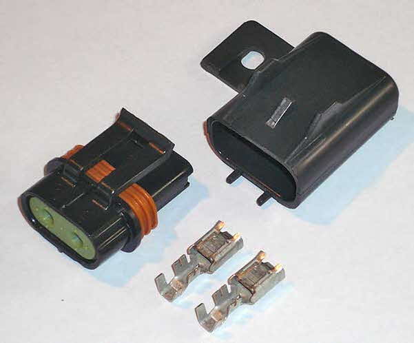
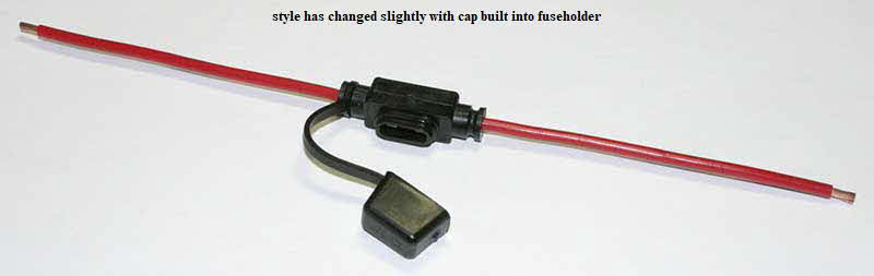
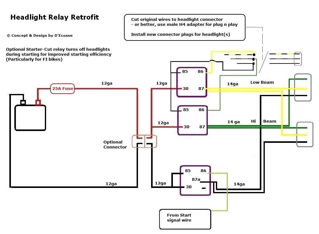
The good news is that the harware (the relays) are already there on board! So nothing to relocate, just add some improved gauge wiring in a slightly different configuration. So this is a really cost-effective upgrade just for the price of a couple of metres 12 ga wire.

There are two parts to the process:
The first is to improve the ground return and regain that lost 1V.
Measuring at the headlight cut relay, I had about 0.225V from the -ve terminal. You could choose to live with this if you want to simplify things, however ideal situation is to run new 12 ga wire to that relay's terminal 30 from battery -ve and from 87a to the common connection point for the headlights. The relay coil connections (85 & 86) remain unchanged. As far as schematic goes, this is identical - just creating a direct path to the battery -ve terminal with a better grade of wire, which should minimize the voltage drop across the return.

Second part: have BOTH lights (for low & main respectively) operate off the relay instead of only one. This again just involves a slight re-wire of the existing relays with some 12 ga wiring. You can simplify things by only changing the output of the relays, leaving the original power input from the Triumph fuse box (optional shown as dashed line); for optimum performance, run a new 12 ga wire to the inputs of these relays.

Schematically, you can see the difference in these simplified diagrams.
(these are actually the 02+ schematics but the 97-01 is essentially the same)

Original Wiring:

717214


Improved wiring:

717215


I plan to make the upgrades to the wiring after the Holiday weekend and will post up the results. But I expect to have somewhere in the region of 14V to each headlight - that is the goal!
That should DOUBLE the light output. We'll see how close it comes! :p

.
 
#2 ·
why ?

Do you guys find the headlamps to be poor for the Triumphs, my 04 Daytona seems okay,I do early morning rides to work in the dark,hardly ever use the HI beam as I never really seem to need it,and these are unlit country roads.Or maybe this is an upgrade not so much cause we need it , but more because it's just something to do.?
 
#4 ·
Do you guys find the headlamps to be poor for the Triumphs, my 04 Daytona seems okay,I do early morning rides to work in the dark,hardly ever use the HI beam as I never really seem to need it....
Surely everyone can use a little more performance, whether brakes hp - or even lighting!
Not a continuing argument that everyone needs to rush out & do this and you are an example of someone who is satisfied with that level of performance.
But for those who are not, or don't know what they are missing, this is simply an inexpensive means of a performance improvement that will make your bike more noticable even in daylight.

What is also a factor is that if anyone wants even more, you have a better baseline system to gain the maximum performance from bulbs better than 'std' H4 lights.
Like '+50' bulbs or even Osram Rally 70/65 bulbs - which will be perfectly safe & efficient with the new wiring scheme.

Could you do a step by step instruction, with pics when you do it. ...
Will indeed provide a photodoc on the process, although it is fairly simple. I'll shoot some before pics of the illuminated foreground before starting, then will repeat when mod is completed.
I may try to do this in stages - use the 'optional' original input supply voltage to relays path before apllying the direct to battery method.
(Already know losing ~ 0.225V between ground and cut-relay then .75V on the ground return between relay & lights so will probably do both those legs immediately)
No picture test for intermediate step - if voltage still being dropped to relay, we'll go ahead & eliminate it. But still capture the data regarding the voltage.

... How long will the bulbs last with the mod?
As you can see in the light-output table table in the first post, bulbs are lifetime rated at 14V so they should last as long as that stated on the box.
Any reduced actual operating voltage will yield longer-than-advertised life of course.

.
 
#5 ·
Great idea!

Ths is a great discovery DEcosse and something I will definately do myself!

I guess my initial thought was similar but different to tri955i - I was wondering if there is a big difference between individual bikes and/or could the voltage drop over time (I am guessing yes....).

So whilst I think this is an excellent and simple mod, there may be varying levels of improvement from bike to bike?

Regardless, like you I ask the question - why settle for second best??
 
#6 · (Edited)
...
I guess my initial thought was similar but different to tri955i - I was wondering if there is a big difference between individual bikes and/or could the voltage drop over time (I am guessing yes....)
........ there may be varying levels of improvement from bike to bike? ...
I think that shouild be fairly consistent - this is simple ohms law - V=I*R
R is (relatively) high because of the small gauge wires used in the harnesses.
Because 'I' is high in the lighting circuit, the volt-drop is relatively substantial.
Design is constant (subtle differences from 97-01 to 02+) so there should be no variability there.
There could be some aging effect from oxidation of terminals etc, one could suppose, but have to say mine all looked pretty pristine
i.e. no losses in mine (and the measured results) that I would have attributed to any aging (odixation) effects.

So I would have to say that I believe this to be a fairly typical result.

It's sinple test that you can do for yourself:
1) start your bike,
2) measure the voltage directly across battery terminals
3) measure voltage across each lamp socket (or nearest connector prior)
4) measure voltage between battery -ve and the common terminal to lamp socket (or nearest connector prior)

Repeat for each lamp (they will likely be different - as shown mine were 1V difference between the relay & direct wired lamps)

Result 3 - Result 2 will give the total volt drop to that lamp
Result 4 is the volt drop from just the return path.

.

Re-work has been completed and here are results!

Well I almost reached my goal of 14V at the headlights - just 2/100th off of 14.00 at 13.98V

My first test was as I had suggested, to do the ground return wire, plus initial stage of relays to lights (leaving original feed from fuse box to the relays)

That actually was not too bad - measured at the lights I got ~ 13.5V. So picked up 2 whole volts on the non-relay circuit and even 1V on the original relay circuit!
I also measured the voltage between the battery -ve terminal and the common at the headlight plug - this was now only 0.17V - down from almost a whole volt previously.

In this condition I could measure almost 0.5V (few 1/100 under) voltage drop between the battery + and the purple wires at the relays (which come from fuse box); so I decided to go ahead and just run a new power feed directly from battery via a new fuse-holder to the relays.
(For your own consideration, you could run new power wires to OEM fuse panel - this was just a whole lot simpler)

After running the new power feeds, I gained back that extra 0.5V.

This is measured directly at the connector plug:

Low Beam:

Image


Hi Beam

717217


.

The resultant pick-up was 2.5V on the non-relay lamp and 1.5V on the original-relay fed lamp.
From the table in the first post, that transpires to a change for the non-relay fed light from 695 to 1356 lumens - 94% more light - almost double!!!!
- on the OEM-relay wired lamp that gained from 924 t0 1356 on - that is an additional 47% more light.

.
 
#7 · (Edited)
Here are the pictures - all were taken at 1/2 sec exposure at f2.8
i.e. all exposed identically

Note that the Lamp reflectors are unchanged, so what you need to look at is not the range of the light, but the intensity of the illuminated areas.

I think they look much whiter and more clear. But as always, pictures don't do justice when showing lighting effects.

Once I get the bodywork all back together, I'll take it out to a quiet country road and get some perspective of that.

717218


Before Low

717219


After Low

717220


Before Hi

717221


After Hi

717222


As mentioned earlier, now that you have the fundamentals of the wiring up to scratch, you can now consider some better bulbs to improve even further.

.
 
#8 · (Edited)
When I started to do the re-wire, it was immediately obvious why there was such a large voltage drop - the OEM wires are extremely small gauge!

Your particular install may vary slightly, whether you have Daytona or S3, 97-01 or 02+ model. But all are essentially same process.

I started at the lamp end of things. On my install, I had previously spliced the wires from the original T509 head-light harness into the 02+ Daytona harness.
So I picked the same point to re-wire my modification.

717223


In my case, yellow is park, black/silver is Hi and black/green is low - of course with each black/silver and black green, one is direct wire and one is from relay. It is unimportant which is which so no need to figure it out.

This shows the connector plugs going to the lamp assemblies which is essentially to what we are re-wiring.

717225


Those are two 4-pin plugs with ground return, Hi, Lo and park wires.
I left the park alone and proceeded to connect new 12 ga cables to the Hi, Lo and Ground return wires.

Here are those wires terminated ready for heatshrink insulation.

717227


And here we are with the 'front' end complete, ready for taping.

717228


I used black 12 ga wire for each line - so it is important to id which is which
I just used a piece of red tape on the low and same on the hi, but with a black stripe from sharpie. That way you can tape up and know what is going on at the relay end of things.

Image


One tip on wire source - I had previously been buying at my local Kragen (O'Neills) auto parts store - EXACT SAME roll at Walmart is $2.95 vs $6.95 at the former!!!!!

Here is front harness complete, taped, ready to route through bike to the relays under seat.

Note the 'free' ends of the old harness - these should be capped off/insulated. We will no longer use any of these wires.
Just match like-like (tie like colours together) and insulate and tape into the harness.
It's more important to tie the black wires together, the Hi & lo signals are inconsequential whether tied together respectively or not.

717230


.
 

Attachments

#9 · (Edited)
Onto the rear and the integration of the new harness into the relays.

Start by identifying the three relays you need - the starter-headlight-cut, the Hi and Lo relays.

717231


Address the starter-cut relay first, which interlocks the ground return from the headlights.

Note: on all three relays we will only be dealing with the switched 'poles' of the relays - all of the coil connection to pins 85 & 86 will remain as-is.
On the starter cut, it is pins 30 & 87a that will be addressed; on the the Hi & Low it will be 30 & 87.

The first thing you need to know about the relay sockets, is how to remove the terminals:

Here is a cartoon that shows how they are latched in:

717232


You insert a tool (open paper clip or similar) from the relay side to depress the latch pin & pull out the wire/terminal from the wire side.

.
With the terminals removed from 30 & 87a, you now need to insert your new harness wire and also a direct wire to battery -ve.
I obtained some new terminal pins at the auto-parts store for the relay sockets.

Terminate the new harness wire from the headlights and also make a new short harness wire with relay connector female terminal on one end and battery ring lug at the other.

Plug these into the relay socket in locations for 87a & 30 (it is not important which is which)
Insulate the terminals that you removed originally and leave them in harness.

717233


Next repeat the process for the Hi & low relays. This time the purple wires (on each relay) will be replaced with a fused supply directly from the battery +. Pull the 15A headlight fuse from the fusebox which will render the purple wires inactive. But insulate and tie back aside regardless.

Then terminate the Hi & Low power wires from new harness into the terminals opposite the new power source. (new source & ouput will be pins 30 & 87 - again it is unimportant which is which)

This image shows 'old' output wire (black/silver) removed from the Hi relay socket, with new harness output ready to re-install

717234


This shows new fused power harness for the Hi & Low relays

717235


And populated into the socket locations of the HI & Lo where the purple wires formerly resided

717236


Complete the process by insulating those terminals removed from the sockets originally

.
 
#10 · (Edited)
And finally, connect the new power line to battery + and the new -ve cable from the starter-cut to their respective battery terminals.

717239


That should be it!
Test & validate all is working correctly.
Your headlights should go out when cranking starter and of course all 4 filaments of the headlights (as well as park lights) should all function as intended.

If you have any specific questions re wire colours or relay ID for your particular model, be glad to help if I can.

.
 
#13 · (Edited)
Sounds like someone is planning a weekend project! :p

How do we know which 15A fuse is for the purple wires?
Fuse #6

Also, where'd you get the 30A housing for the fuse to the positive battery terminal?
I actually prefer the MetricPack 280 or 630 series of sealed fuse-holders
This is source from an excellent vendor on Ebay, MJM National
http://cgi.ebay.com/ebaymotors/Metr...se-Holder-Kit-/360279795792?cmd=ViewItem&pt=Car_Audio_Video&hash=item53e2596850

Or from EasternBeaver - Fuseholders

Image


You can also buy a pre-made ATO/ATC size waterproof fuse-holder at any automotive parts store
Also buy the matching fuse (ideally 25A)

Image


And could you tell me what the wire colors for a 2001 daytona 955i are and how I can tell which relay is for which?...
You want relays 2 & 3 as shown below.

717245


Here are the wire colours and instructions.

The 97-99* is actually much easier than the 02+ because the starter-headlight-cut relay does not switch the ground, but the power - so you only have two relays to re-wire. Simply run a new 12 ga from the headlights back to the battery -ve.

* Edited - the schematic below should be labelled 97-99 - 00 & 01 models conform to same wiring system (switched ground on the starter-cut) as the 02-04 S3.

717244


.
 
#15 ·
timwu said:
..... after I pull fuse #6 which is for 15A, I can put it into the fuse wire to the positive terminal even though you said to put a 30A fuse there? ....
Actually, arising from your question, I realize that 15A is not enough.
I failed to account for situation where you will apply the 'flash' switch - if on low beam, and you 'flash' then all 4 filaments will pull power simultaneously through that fuse.
That load is about 20A so 30A or 25A (better) fuse would be ideal.

(I'll amend the schematics & text accordingly)

Thanks for raising that flag! :p
 
#20 ·
Not in the one I'm looking at!

Triumph is REALY bad about using duplicate colours - note that fuse 'a' (Fuel Pump) is ALSO brown in, Purple out and ALSO a 15A fuse.
To make sure you get the right one, before you start you should pull one of the three 15A fuses - if you get the pump fuse, that will be obvious as you will not hear the pump prime when you turn on ignition.
If you get the correct one, the left main beam will go out.
You should be able to refer to the key inside the fuse-box lid (make sure you are looking at lid in correct orientation)

Image
 

Attachments

#22 · (Edited)
DEcosse, you may be held responsible for me being found frozen in my garage this winter as a apply those mods to my S3. And let me add, when I had the fairing off my HD Roadglide, I found the same small gauge wires to my dual headlights. So it to will be getting a wiring upgrade. What really knocked my socks off, was that the wire to the cigar lighter that a lot of folks think they should use as "Accessory Power" is only 22ga. I'd expected something around 14ga.
And let me ask a question, Can you give a short answer about what looks like a copper ground buss in some of your pics?
 
#23 ·
There's a different wiring scheme in you 08 model wabill - it may not be quite so bad as the previous generations - measure the voltage at your light socket (or the plug immediately before) and compare to battery volts to see how it looks.
You can also just measure the volt drop on the return line alone, by measuring between the battery -ve terminal and the common return at the light socket (or again the connector immediately before)
Do these checks with the engine running, so your battery is not draining, affecting your measurements.

The copper thing (bolted to my subframe) to which I think you are referring is a combination heat-sink/mounting plate for my R/R - the heatsink was to improve things when I had the old OEM R/R - now with the new MOSFET R/R that feature of it is not really necessary. (see the sticky thread for details on the MOSFET R/R)
 
#24 ·
I employed the method above for the Triumph, because the relays already exist on those, so it is unnecessary to add more.
But if anyone is over-whelmed by scope of this project, if you don't mind an extra couple of relays, you can use this method which is a lot simpler to execute:

Image

Indeed this will work for ANY bike and whether or not bike has headlight-cut feature for start etc - it will just mimic whatever the power situation would be as supplied to the lamp.
(Note that these are NEW, additional relays - not the ones already on board)
You are simply going to use the existing power connector to the headlamp, to drive relay coils, which will now switch power directly from the battery
This will be a complete auxiliary harness and indeed no cutting or modification of your OEM harness at all is necessary.
Even simpler if you eliminate the optional intermediate connector and just wire straight through to the relays.

Ideally the relays will be mounted up front, close to the headlights so may work better on a faired bike where you can mount them easily.
You can use a male H4 connector plug to connect to the original headlamp connector - if you have twin lights, you still only use one of them for the 'drive' signal, but connect dual to the outputs to the relays.
For single headlight bikes, it's exactly the same but of course you only have one output from the relay.

If you have a bike that does not presently have a headlight-cut-while-start feature, you can add one simply like this
Although it says TL/SV650, again can be used on any bike - simply identify the correct wire from the start switch as appropriate.

Image


.
 
#25 ·
i replaced most of the wiring on my gsxr and set it up with 2 35w lowbeams and 2 HID for the high. the lows are useless but legal and the high beams are great. about to do the same to the triple i just pickd up. im going to replace all the wiring to make it easier for me to follow and make sure the ballast get 12.5 volts or more so they can come on.
 
#26 ·
I personally would not use HIDs on a motorcycle that does not have projector enclosures designed to use them.
You will get better performance from a good bulb with a quality voltage source (IMO).

On a Speed Triple, the next thing to do to improve would be to fit something like Cibie Reflector shells/lenses to go along with the wiring/bulb upgrades.

http://www.danielsternlighting.com/products/products.html

.
 
#27 ·
Yea i never put hid's ina housing that didnt have a reflector cone in front of the bulb, but they burn much cooler and lower amperage. just kinda harsh for oncomming traffic without the reflector infront of the bulb. im kinda used to them they make cop cars glow in the dark long before u can see them with conventional bulbs.
 
#28 · (Edited)
Update - now installed Philips X-treme Power +80 bulbs

These bulbs made a really significant difference as you will see in the pictures below.

I purchased the Philips bulbs from PowerBulbs in the UK - free World-wide shipping and the best price around from what I could find. Ordered on the 2nd and received exactly one week later on the 9th.

I took a little more trouble with ensuring that the exposures were identical and have included that info for each picture.
What I discovered with my initial pictures, I was shooting in Auto, and although the shutter speed and aperture were the same for the initial shots, the 'after' low beam was actually exposed at lower ISO speed equivalent.
So in fact, in previous before/after composite low beam image above, the after is actually a dis-service, as would have been even better!

Here are the images from original to relay/wiring to Philips progression - note again the anomaly of the reduced ISO for the
'after wiring' pic in the low beam set.

Low - Upgraded Wiring + Philips Xtreme Power

717247


High - Upgraded Wiring + Philips Xtreme Power

717248