This alternative Speedo Sender could be employed by those who have a broken speedo magnet
Triumph won't provide the magnet - which is frequently broken after re-assembly of front wheel after service, tire-change etc - as a separate line-item and you have no option but to purchase a complete speed sender assembly - not cheap!
Now - instead of paying $175 for a new Triumph sender, execute this mod for ~ $25!
The best part is it will never break again!
Also, for anyone who would like to use the late model (05+) wheels on their early models,
And this will also work for those doing fork/wheel swaps for example, where no provision for the OEM speedo drive exists on the replacement wheel.
Note: easier for Sprint - all years use 25mm axle;
02-04 S3 & 02-06 Daytona use 20mm axle so more involved for wheel swap
you have been previously prohibited since the new model has no speedo drive detent in the wheel.
Well, I have the solution for you!
I used a very similar solution on my GSXR fork retrofit to my Mrs SV650 and felt pretty sure that the same method could be employed on the Triumph.
The simple fact is that the sender is nothing more than a Hall-Effect sensor - a magnet creates a field induced current as it sweeps past a detector.
Most bike share a common process but the mechanics of the device and where it is located varies.
Now on the 99-04 series of Sprints (or similar era Speed Triple, Daytona, TT600 etc), you have an electronic speedo that receives its input from the ECM which in turn receives a signal which is generated by a front wheel sender.
On the 05+, the principle is the same although the sender is based on the output shaft and of course the ratio of pulses generated is quite different. The output signal to the instument is CANBUS and quite, quite different, but all we need to concern ourself with is the input to the ECM.
So how to create a signal on an early bike using late model wheels that has neither a device from the transmission or the wheel?
The simplest method is to replicate the action of the wheel driven sender if possible - by using a frequency based on the same rotation diameter (i.e. the wheel!) no additional calibration should be required.
Back to the SV for a moment - we'll use this method as a basis for the swap. The SV happens to use a very similar wheel/axle based sender on the front wheel as the 99-04 Sprints.
When upgrading to GSXR front end, those wheels pose similar problems in that the donor bikes utilize a final output drive sender.
I was able to take a GSXR sender - there are after-market Hall Effect Trigger available, but GSXR sensors are plentiful & cheap off EBay (less than $20) .
I mounted this to a simple bracket using the inside of the fender stanchions and it is triggered off magnets simply epoxied on the rotor.
It works perfectly on the SV!
So - would that work on the Triumph?
Since I had all the bits at my disposal I thought I'd check this out - it's actually been on my agenda to validate this for some time anyway.
I actually have on-hand an old GSXR harness which not only donated the plug that obviously fit the GSXR sender, but also conveniently gave up another which fit the Daytona harness speedo input!
So I made a simple extender cable with each of those connectors on either end.
Then I took the speedo sender off my TL (TL/Hayabusa/GSXR/SV1K all have used the same sender for about last 10 years!) and plugged it in the extender, then the extender into the Daytona harness.
Turned on the Triumph ignition, and per the previously suggested test, just took a magnet and osciallated it back & forth across the sensor face, while monitoring the instrument display.
Bingo! Good reading on the speedo commensurate with the rate at which I was moving the magnet.
So this validates that the process works!
There are 4 magnets used for the Triumphs.
Here's how it came together on the SV - you would use similar for the Triumphs.
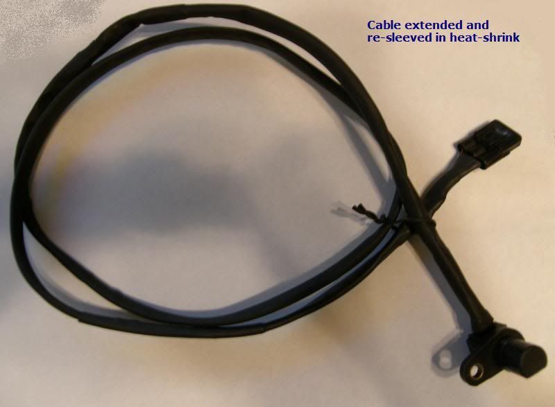
This is the GSXR/TL/Hayabusa/SV1K sensor
(common to all from about 99 - current):
![Image]()
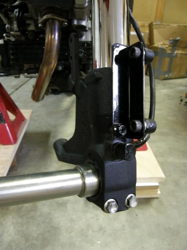
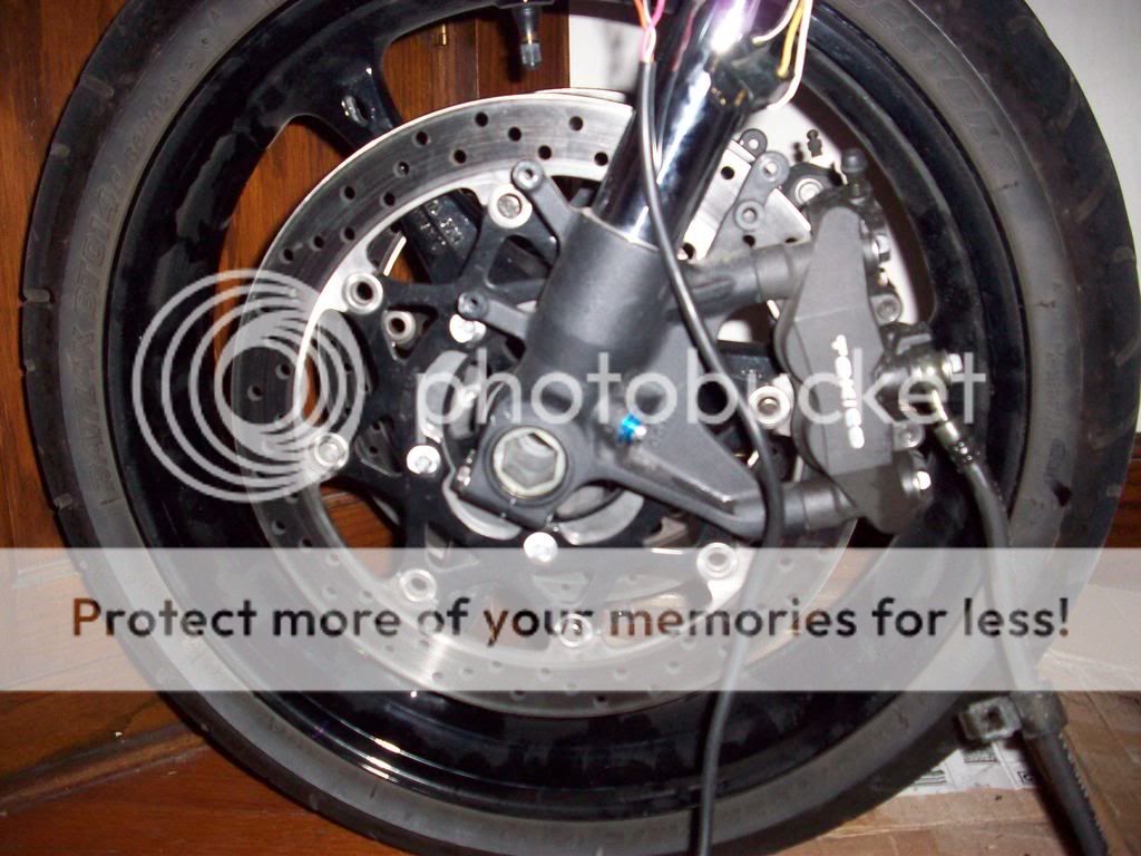
This is the sender mounted on a simple bracket on my SV
- the bracket is mounted to the fender stanchions with modified (very short) screws so that they dont interfere with the actual fender mount screws on the outside of same stanchions:
![Image]()
![Image]()
.
The mounting of the sender will clearly be a little different on the Sprint forks or early Speed Triple/Daytona forks, but should not be very challenging.
The important thing to know is that it will work electronically
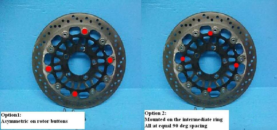
Magnets mounted on the rotor are the triggers.
They just need to be positioned on a radius that sweeps past the sensor location.
This is the source I used for the rare-earth magnets
They are also available on EBay if you do a search
Here is a convenient mounting location in the rotor buttons!
![Image]()
![Image]()
Important Note: You should only use the rotor buttons as a mounting location if you have an equal multiple of 4 and thus can space the magnets at exactly 90 deg intervals.
Spacing the magnets non-symmetrically will result in speedo error.
.
.
.
Here is wiring relationship between the OEM Triumph sender & the Suzuki one
.................Daytona Harness .......Triumph Speed Sensor .........GSXR sender
Power .... Black/Yellow.................. Red/Orange ......................... Black/Red .
Ground.... Black ............................ Black/White ......................... Black/White
Signal ..... White/Blue ...................Pink ...................................... Black
You can use crimps if you're not comfortable soldering - but because the GSXR cable is really short, it will give you bulky cable just up from the sensor.
Best if you can solder and use heat-shrink sleeve over each individual splice, then another heatshrink over whole joint section.
When you splice the sensor cables together you can ignore the first block above (Daytona harness)
From the GSXR sender to the donor Triumph sender cable:
Connect Black/Red to Red/Orange
Connect Black/white to Black/White
Connect Black to Pink
Figure out how you're going to mount sensor first - once you have optimum position for that then the magnets will take care of themselves.
You can make this on either side of course, doesn't matter which leg/rotor you set it up on.
One thing to note is that the magnets MUST be applied with poles in same direction.
Easiest way to do this is to stack them then mark the top of each one with a marker as you peel it off the stack.
Then assemble with the dots all facing out.
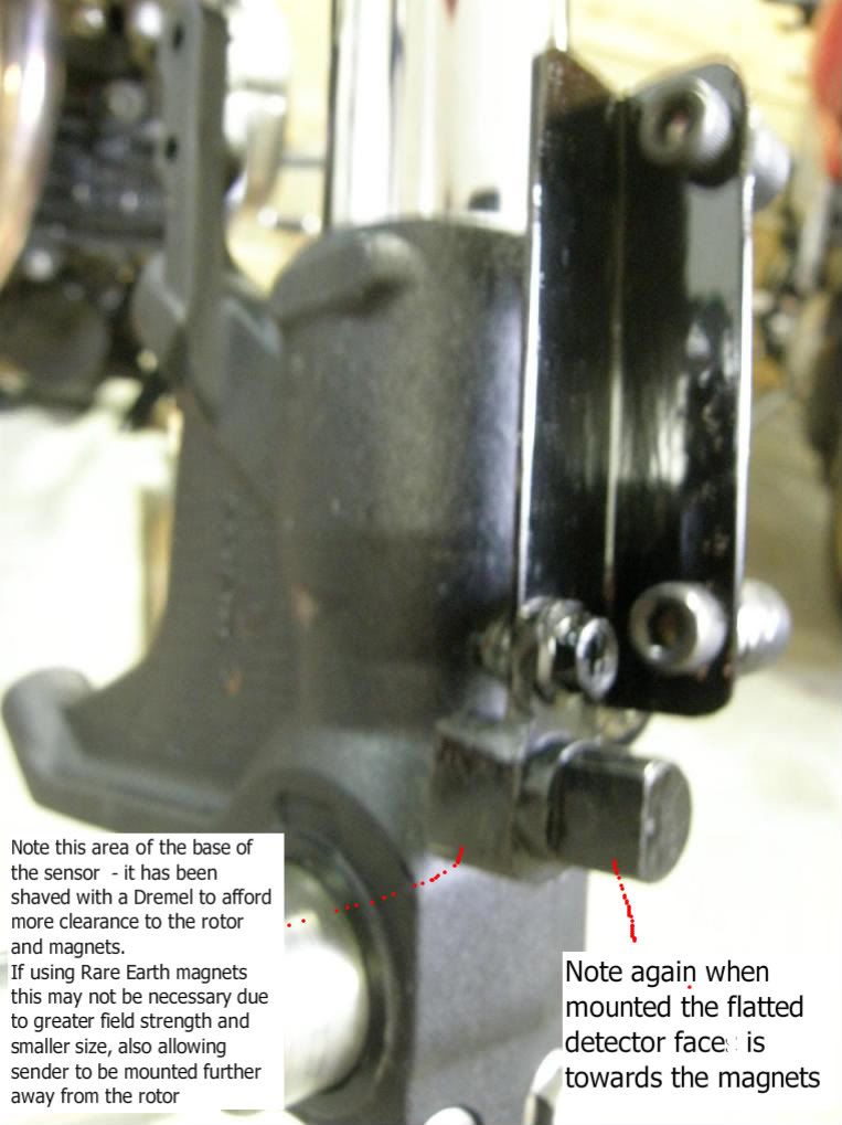
If you can get rare-earth (Neodymium) magnets so much the better - they are small and have really strong field, so should be detected over quite a gap - on my SV set-up they are 1/4" and maybe 5mm away from sensor - with the rare-earth I'm sure they would trigger from further away.
You can actually use any kind of Hall Effect sensor - here is another option -> Cherry GS100701
![Image]()
Another mounting method:
See this really cool mounting concept from Jen A in post # 133 later in the thread - http://www.triumphrat.net/speed-tri...oken-speedo-sender-fix-also-mod-for-05-wheels-on-early-model-4.html#post2005378
EXTREMELY well executed mod!
![Image]()
See the actual post from link to get the full details.
.
.
.
Triumph won't provide the magnet - which is frequently broken after re-assembly of front wheel after service, tire-change etc - as a separate line-item and you have no option but to purchase a complete speed sender assembly - not cheap!
Now - instead of paying $175 for a new Triumph sender, execute this mod for ~ $25!
The best part is it will never break again!
Also, for anyone who would like to use the late model (05+) wheels on their early models,
And this will also work for those doing fork/wheel swaps for example, where no provision for the OEM speedo drive exists on the replacement wheel.
Note: easier for Sprint - all years use 25mm axle;
02-04 S3 & 02-06 Daytona use 20mm axle so more involved for wheel swap
you have been previously prohibited since the new model has no speedo drive detent in the wheel.
Well, I have the solution for you!
I used a very similar solution on my GSXR fork retrofit to my Mrs SV650 and felt pretty sure that the same method could be employed on the Triumph.
The simple fact is that the sender is nothing more than a Hall-Effect sensor - a magnet creates a field induced current as it sweeps past a detector.
Most bike share a common process but the mechanics of the device and where it is located varies.
Now on the 99-04 series of Sprints (or similar era Speed Triple, Daytona, TT600 etc), you have an electronic speedo that receives its input from the ECM which in turn receives a signal which is generated by a front wheel sender.
On the 05+, the principle is the same although the sender is based on the output shaft and of course the ratio of pulses generated is quite different. The output signal to the instument is CANBUS and quite, quite different, but all we need to concern ourself with is the input to the ECM.
So how to create a signal on an early bike using late model wheels that has neither a device from the transmission or the wheel?
The simplest method is to replicate the action of the wheel driven sender if possible - by using a frequency based on the same rotation diameter (i.e. the wheel!) no additional calibration should be required.
Back to the SV for a moment - we'll use this method as a basis for the swap. The SV happens to use a very similar wheel/axle based sender on the front wheel as the 99-04 Sprints.
When upgrading to GSXR front end, those wheels pose similar problems in that the donor bikes utilize a final output drive sender.
I was able to take a GSXR sender - there are after-market Hall Effect Trigger available, but GSXR sensors are plentiful & cheap off EBay (less than $20) .
I mounted this to a simple bracket using the inside of the fender stanchions and it is triggered off magnets simply epoxied on the rotor.
It works perfectly on the SV!
So - would that work on the Triumph?
Since I had all the bits at my disposal I thought I'd check this out - it's actually been on my agenda to validate this for some time anyway.
I actually have on-hand an old GSXR harness which not only donated the plug that obviously fit the GSXR sender, but also conveniently gave up another which fit the Daytona harness speedo input!
So I made a simple extender cable with each of those connectors on either end.
Then I took the speedo sender off my TL (TL/Hayabusa/GSXR/SV1K all have used the same sender for about last 10 years!) and plugged it in the extender, then the extender into the Daytona harness.
Turned on the Triumph ignition, and per the previously suggested test, just took a magnet and osciallated it back & forth across the sensor face, while monitoring the instrument display.
Bingo! Good reading on the speedo commensurate with the rate at which I was moving the magnet.
So this validates that the process works!
There are 4 magnets used for the Triumphs.
Here's how it came together on the SV - you would use similar for the Triumphs.
This is the GSXR/TL/Hayabusa/SV1K sensor
(common to all from about 99 - current):
This is the sender mounted on a simple bracket on my SV
- the bracket is mounted to the fender stanchions with modified (very short) screws so that they dont interfere with the actual fender mount screws on the outside of same stanchions:
.
The mounting of the sender will clearly be a little different on the Sprint forks or early Speed Triple/Daytona forks, but should not be very challenging.
The important thing to know is that it will work electronically
Magnets mounted on the rotor are the triggers.
They just need to be positioned on a radius that sweeps past the sensor location.
This is the source I used for the rare-earth magnets
They are also available on EBay if you do a search
Here is a convenient mounting location in the rotor buttons!

Important Note: You should only use the rotor buttons as a mounting location if you have an equal multiple of 4 and thus can space the magnets at exactly 90 deg intervals.
Spacing the magnets non-symmetrically will result in speedo error.
.
.
.
Here is wiring relationship between the OEM Triumph sender & the Suzuki one
.................Daytona Harness .......Triumph Speed Sensor .........GSXR sender
Power .... Black/Yellow.................. Red/Orange ......................... Black/Red .
Ground.... Black ............................ Black/White ......................... Black/White
Signal ..... White/Blue ...................Pink ...................................... Black
You can use crimps if you're not comfortable soldering - but because the GSXR cable is really short, it will give you bulky cable just up from the sensor.
Best if you can solder and use heat-shrink sleeve over each individual splice, then another heatshrink over whole joint section.
When you splice the sensor cables together you can ignore the first block above (Daytona harness)
From the GSXR sender to the donor Triumph sender cable:
Connect Black/Red to Red/Orange
Connect Black/white to Black/White
Connect Black to Pink
Figure out how you're going to mount sensor first - once you have optimum position for that then the magnets will take care of themselves.
You can make this on either side of course, doesn't matter which leg/rotor you set it up on.
One thing to note is that the magnets MUST be applied with poles in same direction.
Easiest way to do this is to stack them then mark the top of each one with a marker as you peel it off the stack.
Then assemble with the dots all facing out.
If you can get rare-earth (Neodymium) magnets so much the better - they are small and have really strong field, so should be detected over quite a gap - on my SV set-up they are 1/4" and maybe 5mm away from sensor - with the rare-earth I'm sure they would trigger from further away.
You can actually use any kind of Hall Effect sensor - here is another option -> Cherry GS100701

Another mounting method:
See this really cool mounting concept from Jen A in post # 133 later in the thread - http://www.triumphrat.net/speed-tri...oken-speedo-sender-fix-also-mod-for-05-wheels-on-early-model-4.html#post2005378
EXTREMELY well executed mod!

See the actual post from link to get the full details.
.
.
.
") will the distance from the hub make a huge difference, I am going to mount the magnets on the dics rotor near as possible to the spindle, can I simply remove the Suzuki plug and fit bullet conectors to hook it into the triumph harness?
will the distance from the hub make a huge difference, I am going to mount the magnets on the dics rotor near as possible to the spindle, can I simply remove the Suzuki plug and fit bullet conectors to hook it into the triumph harness?