Downloadable pdf Guide to Sprint Valve Clearance Checking and Adjustment
The original posts in this thread have lost some value due to lack of images. Links to images were removed when this site was upgraded leaving only blank spaces between the descriptive text. To overcome this issue I have put the original content, including photos, into the attached pdf file. This has added benefit since it can be downloaded, printed or viewed on a computer or phone more easily than the original post.
Attachments
Adjusting 1050 Valve Clearances – Part 1 - Preparation to Part 5 Notes
Adjusting 1050 Valve Clearances – Part 1
For anyone considering doing this job here are details of work I did recently to check and adjust valve clearances on my 2006 Sprint ST 1050 (22,000+ miles). I’ve posted this thread and photos to help others become familiar with the process – it is not intended to be a substitute for a maintenance manual.
This write-up begins with the fairing, tank and airbox already removed to gain access to the cylinder head area. If you need a write up for that part of the job then I suggest you go no further (click here instead).
Method Statement
A general clean up was required before starting work to ensure no dirt got into exposed engine internals. Some components were removed to allow removal of the cam cover. Spark plugs were removed to eliminate compression resistance. The inspection plate was removed from the right hand crank cover to allow the engine to be rotated using the crankshaft end bolt. After removal of the cam cover valve clearances were checked.
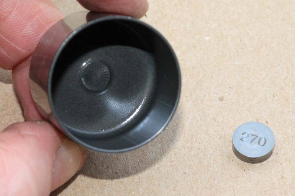
Some adjustment was needed so the camshafts had to be removed. That required removal of the cam chain tensioner. Following camshaft removal valve tappet buckets (followers) and shims were removed. Existing shims were measured and that information was used to determine the correct thicknesses of replacement shims needed to bring valve clearances back to a desired value.
Correct thickness shims were placed over the valve head and the tappet buckets were refitted in the cylinder head. The cams were refitted, cam chain put back in place and valve clearances rechecked. After confirming that the new clearances were within range, remaining parts were reassembled.
Tools required
In addition to the regular selection of sockets and wrenches, the following were required:
Replacement Parts

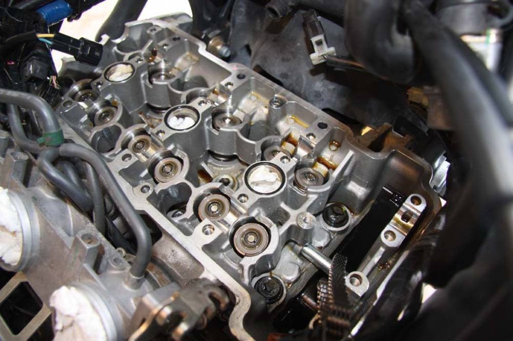
Camshaft area opened ready for valve checking - note round plug tower seals left in place

The original posts in this thread have lost some value due to lack of images. Links to images were removed when this site was upgraded leaving only blank spaces between the descriptive text. To overcome this issue I have put the original content, including photos, into the attached pdf file. This has added benefit since it can be downloaded, printed or viewed on a computer or phone more easily than the original post.
Attachments
- Triumph Sprint 1050 Valve Clearance Check and Adjustment.pdf
2.8 MBViews: 3
Adjusting 1050 Valve Clearances – Part 1 - Preparation to Part 5 Notes
Adjusting 1050 Valve Clearances – Part 1
For anyone considering doing this job here are details of work I did recently to check and adjust valve clearances on my 2006 Sprint ST 1050 (22,000+ miles). I’ve posted this thread and photos to help others become familiar with the process – it is not intended to be a substitute for a maintenance manual.
This write-up begins with the fairing, tank and airbox already removed to gain access to the cylinder head area. If you need a write up for that part of the job then I suggest you go no further (click here instead).
Method Statement
A general clean up was required before starting work to ensure no dirt got into exposed engine internals. Some components were removed to allow removal of the cam cover. Spark plugs were removed to eliminate compression resistance. The inspection plate was removed from the right hand crank cover to allow the engine to be rotated using the crankshaft end bolt. After removal of the cam cover valve clearances were checked.
Some adjustment was needed so the camshafts had to be removed. That required removal of the cam chain tensioner. Following camshaft removal valve tappet buckets (followers) and shims were removed. Existing shims were measured and that information was used to determine the correct thicknesses of replacement shims needed to bring valve clearances back to a desired value.
Correct thickness shims were placed over the valve head and the tappet buckets were refitted in the cylinder head. The cams were refitted, cam chain put back in place and valve clearances rechecked. After confirming that the new clearances were within range, remaining parts were reassembled.
Tools required
In addition to the regular selection of sockets and wrenches, the following were required:
- Feeler gauges (recommend offset gauge similar to Craftsman 26 Leaf Offset Gauge).
- 8mm hex bit or key to rotate crank.
- 6mm hex bit to torque cam cover bolts.
- Torque wrench (range to include settings from 9Nm to 23Nm).
- T30 Torx bit to remove/refit cam chain block.
- Magnetic pickup tool or other means to lift out tappet buckets.
- Micrometer.
Replacement Parts
- Shims for adjusting valve clearances – sizes determined by measurement of existing shims.
- Cam chain tensioner gasket (there is also a sealing washer on the center nut but it is not listed as a separate part on the Triumph parts list).
- Silicone sealer for corners of cam cover.
- Small quantity of fresh engine oil for re-assembly / top up on completion.
- Plenty of paper towels.
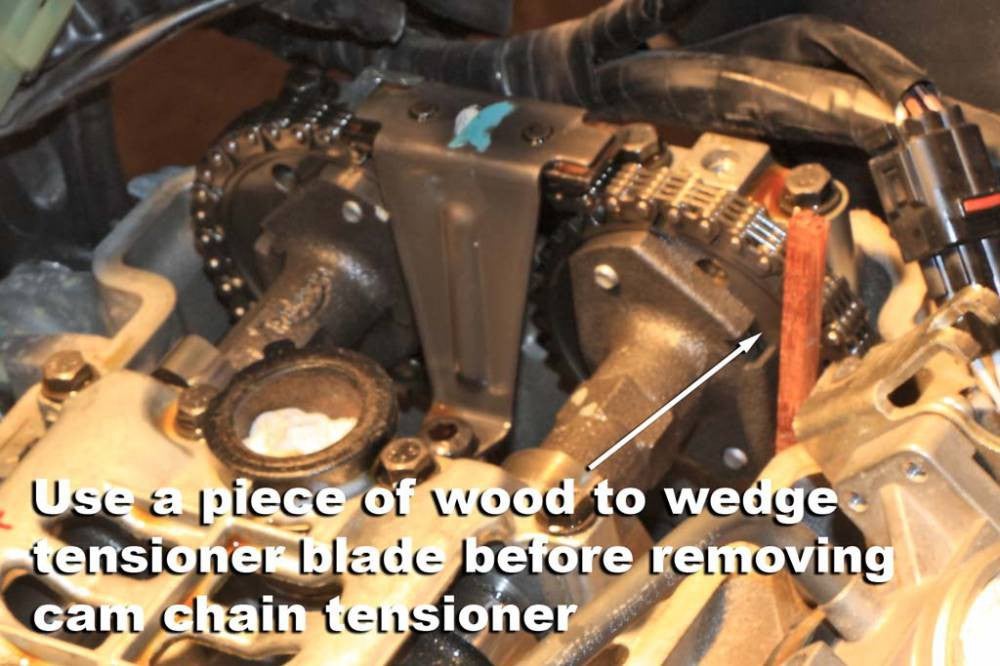
- Piece of wood to wedge cam chain tensioner blade when removing tensioner (not required if not removing cams). With hindsight I feel a clean offcut piece of hosepipe may work better.
- The bike was washed prior to starting any work. After gaining access to the cylinder head area I did a further clean up using compressed air to remove loose debris, followed by a general wipe around to provide a clean work area.
- Next, the throttle cables were removed from the throttle bodies and moved out of the way.
- I marked cylinder numbers on the spark plug coils before pulling them off the plugs.
- My bike has the original SAI system in place. I disconnected the 3 hoses from the valve covers.
- The manual says remove the air deflector shield. That’s not necessary – I simply moved it out of the way.
- I used more blasts of compressed air to blow any loose dirt out of the spark plug wells. After removing the spark plugs I rolled up some paper towel into the spark plug wells to prevent ingress of dirt.
- I removed the inspection plate from the right hand crank cover to allow the engine to be rotated using the crankshaft end bolt.
- Some wires and pipes were moved out of the way to make removal of the cam cover easier.
- I loosened the cam cover bolts in the recommended sequence then removed them (see Note 2).
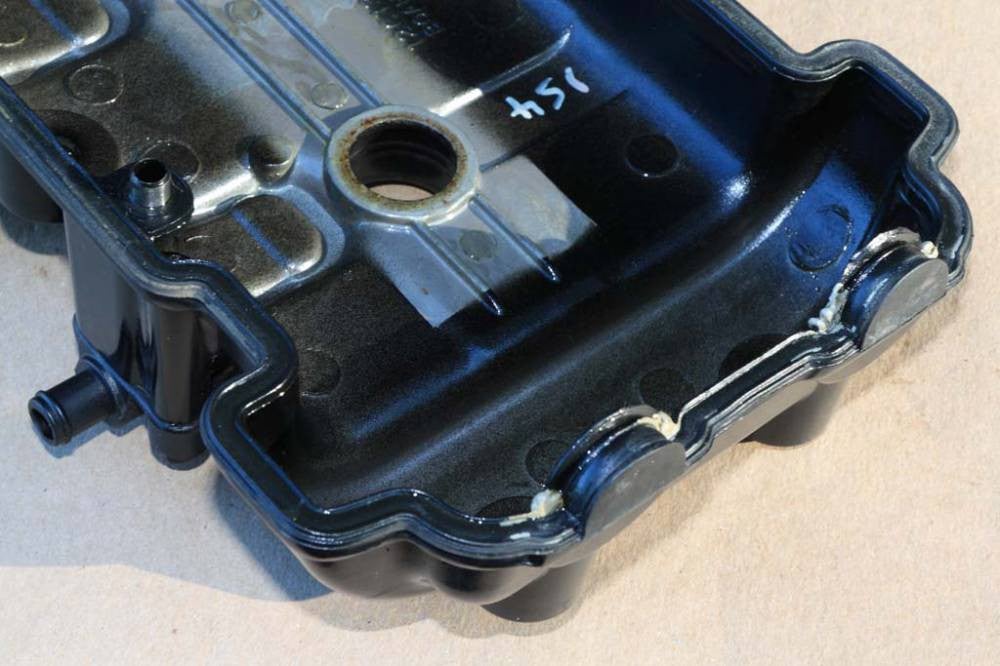
- A light tap with a rubber mallet released the cam cover. It was finally removed taking care not to lose the SAI dowels when lifting the cover off – they may come out attached to the cover or could remain in place in the cylinder head.
- There are 3 round seals around the plug towers. I left them in place to avoid the risk of forgetting to put them back.
Camshaft area opened ready for valve checking - note round plug tower seals left in place


") . if I had not seen this post, I wouldn't have the courage to do this job.
. if I had not seen this post, I wouldn't have the courage to do this job.