Downloadable pdf Guide to TuneECU TPS and ISC Stepper Adjustment
The original posts in this thread have lost some value due to lack of images. Links to images were removed when this site was upgraded leaving only blank spaces between the descriptive text. To overcome this issue I have put the original content, including photos, into the attached pdf file. This has added benefit since it can be downloaded, printed or viewed on a computer or phone more easily than the original post.
Attachments
---------------------------------------------------------------------------------------------------------------------------------------------------------------
TuneECU TPS and ISC Stepper Adjustment
On the “Tests” page of TuneECU there is a menu option labeled “Adjust ISCV”. It provides a means to check and adjust the TPS (Throttle Position Sensor) and ISC (Idle Speed Control) Stepper Motor. TuneECU user information does not provide detailed instructions for this so I’ve posted a description based on my 2006 Sprint ST 1050 with Keihin ECU. I’ve made no attempt to highlight differences for other models. At the end there is additional information for about the secondary throttle used on the Triumph Daytona 600, Daytona 650 and Rocket III.
TuneECU can be used to check and adjust TPS and ISC in three basic steps each accessed by double-clicking “Adjust ISCV” in turn:
OK, that’s a basic description. For those who want to know more read on and I’ll describe at length with photos and other information.
TPS and ISC adjustments are not regular maintenance items and should only be necessary if those components are replaced or found to be operating out of range (that might be sign of imminent failure). If you’re like me you’ll fiddle anyway out of curiosity and a desire to get the settings bang-on.
Checks can be carried out by simply hooking up TuneECU and reading the output voltages without removing the tank, airbox, etc. Just be sure that the throttle cables have sufficient slack so they don’t interfere with the throttles moving to the fully-closed position. I checked mine when the whole area was open and throttle cables disconnected for other maintenance.
The first step is to get a baseline TPS voltage by driving the throttles to the fully-closed position. With TuneECU connected to the bike and ignition on (but engine not running) go to the “Tests” page and double click “Adjust ISCV”.

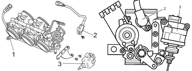
Confirm the “Adjust ISCV?” request. The Cyl 3 MP dial will change to a TPS Voltage indicator. TuneECU will send a command to move the throttles to the fully-closed position. If these checks are being performed because a new stepper motor has been fitted check the clearance between the idle speed control lever and the roller on the throttle cam. Clearance should be 0.5mm.

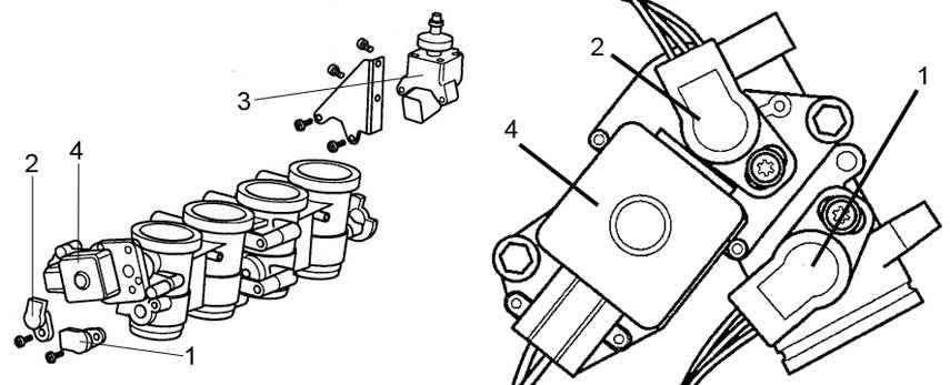
With the throttles still in the fully-closed position the TPS voltage should be 0.60V (+/- 0.02V). If the voltage is outside the range 0.58V – 0.62V adjustment is made by rotating the TPS, located on the left side of the throttle bodies.

On my Sprint access to the TPS holding screws is blocked by the frame. If adjustment is required the easiest way (for me) to do it is to simply remove the throttle body assembly. The TPS holding screws are a Tamper Resistant Torx screw – a T20H Security Torx bit is required. You might consider replacing them with Allen head screws (M4x10) so that a shortened Allen wrench can be used for future adjustments with throttle bodies in place. I didn’t because I don’t expect to adjust my TPS again.
With the screws slackened off slightly the TPS is moved until the required 0.60V is shown on the TuneECU display. The TPS is very sensitive to movement so check the voltage again after re-tightening the screws. Avoid over-tightening the screws – the specified torque is only 3.5Nm so be careful.

If all is OK double-click on “Adjust ISCV” again. TuneECU will send a command to drive the stepper motor to the fully-open position. The TPS voltage should now be the previous reading plus 0.15V. In my screenshot the previous reading was 0.60V so now I was now looking for a reading of 0.75V. A tolerance of +/- 0.05V is allowed so a voltage range of 0.70V – 0.80V is acceptable.
Note: the factory manual for my Sprint 1050 (Keihin ECU) says "On pressing the validation key, the diagnostic tool will send a command that drives the throttles to the fully open position". That is incorrect; only the stepper motor is driven to the fully-open position (thanks to surya for clarifying that in an earlier thread).

If adjustment is required move the adjuster nut to set the position of the stepper arm/idle speed control lever. Be aware that this will change the clearance between the idle speed control lever and the roller on the throttle cam that was measured earlier. The 0.5mm clearance should correspond with 0.75V TPS reading. If they do not correspond then a decision must be made to set one or the other. This setting will affect the throttle position for engine starts so if you experience starting issues with 0.75V set then I’d suggest going back and adjusting the stepper arm to the correct clearance.
![Image]()
When all the correct numbers are achieved double click “Adjust ISCV” again. This will automatically start the “Reset Adaption” sequence – the same process required after a new tune is loaded to the ECU. This does not apply new adaption values; it simply resets them to their start point. To “learn” new adaption values the engine must be run to establish settings for throttle position and fuel trims to achieve correct idle speed control.
Update: from Version 1.9.10 of TuneECU resetting adaption values no longer occurs automatically. Resetting adaptions must be initiated separately using the “Reset Adaption” command (or from the menu bar select “ECU> Reset Adaption”). Resetting adaption values should not be necessary if no adjustments were made.
Adaption cannot begin until the engine reaches normal operating temperature of 90ºC. The whole process can take 10 - 15 minutes during which time the idle speed may be erratic. When adaption is complete the “TPS” indicator at the bottom of the TuneECU screen will turn green. Adaption is a continuous process during normal operation but using “Reset Adaption” is a method to force adaption to take place.
The factory manual says “Several forced adaptions may be necessary to fully adapt an individual motorcycle”.
Another method to force adaption to place is often referred to as the “12 minute tune”. To force adaption this way:
Contd….
The original posts in this thread have lost some value due to lack of images. Links to images were removed when this site was upgraded leaving only blank spaces between the descriptive text. To overcome this issue I have put the original content, including photos, into the attached pdf file. This has added benefit since it can be downloaded, printed or viewed on a computer or phone more easily than the original post.
Attachments
- Triumph TPS and ISC Adjustment with Addendum.pdf
1.6 MBViews: 1
---------------------------------------------------------------------------------------------------------------------------------------------------------------
TuneECU TPS and ISC Stepper Adjustment
On the “Tests” page of TuneECU there is a menu option labeled “Adjust ISCV”. It provides a means to check and adjust the TPS (Throttle Position Sensor) and ISC (Idle Speed Control) Stepper Motor. TuneECU user information does not provide detailed instructions for this so I’ve posted a description based on my 2006 Sprint ST 1050 with Keihin ECU. I’ve made no attempt to highlight differences for other models. At the end there is additional information for about the secondary throttle used on the Triumph Daytona 600, Daytona 650 and Rocket III.
TuneECU can be used to check and adjust TPS and ISC in three basic steps each accessed by double-clicking “Adjust ISCV” in turn:
- Move the throttles to a fully closed position and check TPS voltage. Adjust TPS position if necessary.
- Drive the stepper motor to fully opened and check TPS voltage. Adjust stepper arm/lever if necessary.
- Reset adaptions. This resets adaption values to their start point. The engine must be run to “learn” new adaption values.
OK, that’s a basic description. For those who want to know more read on and I’ll describe at length with photos and other information.
TPS and ISC adjustments are not regular maintenance items and should only be necessary if those components are replaced or found to be operating out of range (that might be sign of imminent failure). If you’re like me you’ll fiddle anyway out of curiosity and a desire to get the settings bang-on.
Checks can be carried out by simply hooking up TuneECU and reading the output voltages without removing the tank, airbox, etc. Just be sure that the throttle cables have sufficient slack so they don’t interfere with the throttles moving to the fully-closed position. I checked mine when the whole area was open and throttle cables disconnected for other maintenance.
The first step is to get a baseline TPS voltage by driving the throttles to the fully-closed position. With TuneECU connected to the bike and ignition on (but engine not running) go to the “Tests” page and double click “Adjust ISCV”.
Confirm the “Adjust ISCV?” request. The Cyl 3 MP dial will change to a TPS Voltage indicator. TuneECU will send a command to move the throttles to the fully-closed position. If these checks are being performed because a new stepper motor has been fitted check the clearance between the idle speed control lever and the roller on the throttle cam. Clearance should be 0.5mm.
With the throttles still in the fully-closed position the TPS voltage should be 0.60V (+/- 0.02V). If the voltage is outside the range 0.58V – 0.62V adjustment is made by rotating the TPS, located on the left side of the throttle bodies.
On my Sprint access to the TPS holding screws is blocked by the frame. If adjustment is required the easiest way (for me) to do it is to simply remove the throttle body assembly. The TPS holding screws are a Tamper Resistant Torx screw – a T20H Security Torx bit is required. You might consider replacing them with Allen head screws (M4x10) so that a shortened Allen wrench can be used for future adjustments with throttle bodies in place. I didn’t because I don’t expect to adjust my TPS again.
With the screws slackened off slightly the TPS is moved until the required 0.60V is shown on the TuneECU display. The TPS is very sensitive to movement so check the voltage again after re-tightening the screws. Avoid over-tightening the screws – the specified torque is only 3.5Nm so be careful.
If all is OK double-click on “Adjust ISCV” again. TuneECU will send a command to drive the stepper motor to the fully-open position. The TPS voltage should now be the previous reading plus 0.15V. In my screenshot the previous reading was 0.60V so now I was now looking for a reading of 0.75V. A tolerance of +/- 0.05V is allowed so a voltage range of 0.70V – 0.80V is acceptable.
Note: the factory manual for my Sprint 1050 (Keihin ECU) says "On pressing the validation key, the diagnostic tool will send a command that drives the throttles to the fully open position". That is incorrect; only the stepper motor is driven to the fully-open position (thanks to surya for clarifying that in an earlier thread).
If adjustment is required move the adjuster nut to set the position of the stepper arm/idle speed control lever. Be aware that this will change the clearance between the idle speed control lever and the roller on the throttle cam that was measured earlier. The 0.5mm clearance should correspond with 0.75V TPS reading. If they do not correspond then a decision must be made to set one or the other. This setting will affect the throttle position for engine starts so if you experience starting issues with 0.75V set then I’d suggest going back and adjusting the stepper arm to the correct clearance.

When all the correct numbers are achieved double click “Adjust ISCV” again. This will automatically start the “Reset Adaption” sequence – the same process required after a new tune is loaded to the ECU. This does not apply new adaption values; it simply resets them to their start point. To “learn” new adaption values the engine must be run to establish settings for throttle position and fuel trims to achieve correct idle speed control.
Update: from Version 1.9.10 of TuneECU resetting adaption values no longer occurs automatically. Resetting adaptions must be initiated separately using the “Reset Adaption” command (or from the menu bar select “ECU> Reset Adaption”). Resetting adaption values should not be necessary if no adjustments were made.
Adaption cannot begin until the engine reaches normal operating temperature of 90ºC. The whole process can take 10 - 15 minutes during which time the idle speed may be erratic. When adaption is complete the “TPS” indicator at the bottom of the TuneECU screen will turn green. Adaption is a continuous process during normal operation but using “Reset Adaption” is a method to force adaption to take place.
The factory manual says “Several forced adaptions may be necessary to fully adapt an individual motorcycle”.
Another method to force adaption to place is often referred to as the “12 minute tune”. To force adaption this way:
- Ensure the coolant is at ambient temperature
- Start the engine and allow it to warm WITHOUT TOUCHING THE THROTTLE until the cooling fan comes on.
- Leave the engine to idle for a further 12 minutes.
Contd….